creep-fatigue interaction test methods and models|A robust life prediction model for a range of materials under creep : dealer Creep-fatigue interaction behavior of ferritic steels and austenitic stainless-steels — covers properties, test methods and the latest models for applying the test data to components. 11 de dez. de 2023 · Wyylde dictionary. Modified on Mon, 11 Dec 2023 at 03:19 PM. Wyylde is a whole community with as many followers and their own vocabulary. To .
{plog:ftitle_list}
WEBGeorge M. Thomas Akron Beacon Journal. While Strays is categorized as a comedy, writer Dan Perrault (American Vandal) relies primarily on sex and toilet humor to bring on the laughs. October 10 .
Creep-fatigue interaction behavior of ferritic steels and austenitic stainless-steels — covers properties, test methods and the latest models for applying the test data to components.Creep-fatigue interaction behavior of ferritic steels and austenitic stainless-steels — covers properties, test methods and the latest models for applying the test data to componentsThe creep–fatigue interaction behavior of materials is frequently simulated in the laboratory by high-temperature low-cycle fatigue (HTLCF) or creep-fatigue crack growth (CFCG) tests with . The applicability of Chaboche non-linear creep-fatigue interaction model to predict creep-fatigue and TMF lives for thermoplastic composites was investigated. A frequency term .
The papers focus on several important areas concerning experimental and design aspects related to creep and fatigue deformation, creep-fatigue interaction, fatigue crack . We present detailed analyses of dwell characteristics of various waveforms of creep fatigue interaction tests performed on the nickel-based superalloy IN 718. We discuss the .
This paper develops a robust creep-fatigue interaction (CFI) life prediction model which is superior to the existing methods. Specifically, the newly proposed creep damage . Typically such diagrams are constructed from the results of cyclic/hold (LCF with hold time) creep-fatigue tests or thermo-mechanical fatigue (TMF) tests, which indicate the .
Creep Fatigue Interaction under Different Test Variables:

Holdsworth, S.R. Component assessment data requirements from creep-fatigue tests. In Creep Fatigue Interactions: Test Methods and Models; ASTM-STP 1539; ASTM: West Conshohocken, PA, USA, 2011; pp. 1–14. .Creep-Fatigue Interactions: Test Methods and Models. By Ashok Saxena, Ashok Saxena 1. University of Arkansas, Fayette, AR, USA, Symposium Co-Chair and JAI Guest Editor. Search for other works by this author on: . Creep-Fatigue Interactions: Test Methods and Models. Ed. Saxena, A, & Dogan, . Abstract. Different approaches for modelling creep–fatigue (CF) interaction are used on strain controlled creep fatigue data of 9Cr–1Mo-VNb (P91) steel and assessed with the target of finding suitable candidates for use in design rules. The assessed models include time, ductility, and strain energy-based creep-fatigue interaction methods and two simplified .
Abstract. In this work, improved creep-fatigue life prediction models based on time fraction (TF) and ductility exhaustion (DE) rule are established for creep-fatigue life prediction of components at elevated temperatures. Cyclic softening/hardening and stress relaxation models for cyclic softening/hardening material are incorporated in the model. .
The finite element method is employed to optimize the geometry and dimensions of a bolt-hole simulation model (BHSM). . in the interpretation of the CGR in simulation models under creep-fatigue interaction, we will apply classical elastic stress intensity Factor K 1, . (fatigue and creep-fatigue interaction) and test temperature. The low . Creep, Fatigue and Creep–Fatigue Interaction are among the major life limiting factors affecting the deformation and damage behaviour of components used in several high temperature applications including nuclear, aerospace, petrochemical and offshore industries.A thorough understanding of the material behaviour under the above loading conditions is .Creep-fatigue (CF) damage can be evaluated using the rules and guidelines provided in the existing design codes, such as ASME III NH, RCC-MRx and BS-R5. Commonly the rules are based on the creep-fatigue interaction diagram and the methods differ in the way how the creep and fatigue damage fractions are calculated.Creep-Fatigue Interactions: Test Methods and Models. Ed. Saxena, A, & Dogan, B. 100 Barr Harbor Drive, PO Box C700, West Conshohocken, PA 19428-2959: ASTM .
Creep-Fatigue Interactions: Test Methods and Models. Ed. Saxena, A, & Dogan, B. 100 Barr Harbor Drive, PO Box C700, West Conshohocken, PA 19428-2959: ASTM International, 2011. . Creep-Fatigue Interactions: Test Methods and Models. A Model for Predicting Low Cycle Fatigue Life under Creep-Fatigue Interaction. The simultaneous appearance of creep voids and fatigue striations indicates a strong interaction between fatigue and creep, resulting in creep damage that reduces the fatigue life of CFI tests. Among the different hold directions, the combination of tensile and compressive hold ( Fig. 13 (e)) exhibits the highest number of creep voids, thus . Another method is the nonlinear approach, which describes the total damage model by coupling creep and fatigue damage (Zhao et al., 2019). This paper implements the creep-fatigue interaction damage model using a nonlinear summation approach, as .
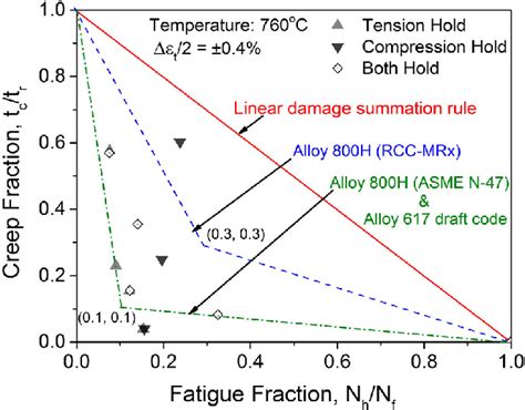
Studying the creep–fatigue interaction of the coarse-grained soil (CGS) is very important for safety assessment and disaster prevention in subgrade engineering. Current research work is mainly focused on single creep or fatigue deformation. In this paper, a new creep–fatigue interaction model is established to predict the creep–fatigue interaction . In recent years, scholars have studied the creep-fatigue damage mechanism and life prediction of different materials or structures. In terms of creep-fatigue damage mechanism, Xiao Y et al. [3] carried out low-cycle fatigue-creep tests of FGH96 powder superalloy used in aero-engine turbine disk at 550℃ for different load holding time and studied the fracture mode . In addition to the method of separate calculation of fatigue and creep damage, the established design codes also include the use of CFI diagram, where a bilinear relationship is recommended by ASME Section III and RCC-MRx design codes [24], [25].As shown in Fig. 1, the ordinate axis (creep damage) of the CFI diagram is defined by the TF method while fatigue .
3.2 Creep–fatigue–environment interactions. Several models for creep–fatigue interactions (Saxena et al. 1981; . 5.2 Creep–fatigue crack growth test methods. ASTM Standard E2760-10 addresses the standard method for characterizing the creep–fatigue crack growth behavior. Areas of advancement of these methods include the following.
where σ 1 is the maximum principal stress, σ h the average of the principal stresses and σ e the effective stress. γ 1, γ 2 and γ 3 are constants that are fitted to creep rupture data under multi-axial conditions. It has been shown that Eq. () can be used to describe experimental data in a number of cases.However, it turns out that different authors give .
Creep–fatigue interaction damage evolution of the P91 steel is investigated and a creep–fatigue damage model has been identified by stress controlled creep–fatigue interaction test of the P91 Steel, which the range of the mean strain acts as the damage parameter defining the damage variable D. The parameters in the model have clear . The Simplified Model Test (SMT) approach is an alternative creep-fatigue evaluation method that no longer requires the use of the damage interaction diagram, or D-diagram. The reason is that the combined effects of creep and fatigue are accounted for in the test data by means of a SMT specimen that is designed to replicate or bound the stress and .Upon normalizing the fatigue life and creep life of the salt numerical model under creep-fatigue tests with different stress intervals, the creep-fatigue interaction diagram is obtained (Fig. 9). The normalized life points from the PFC simulation fall below the straight dashed line representing the linear cumulative damage rule, indicating a .
Under the interaction of creep and fatigue, the service life of parts is 1~2 orders of magnitude lower than that under pure creep and pure fatigue . Therefore, interaction between creep and fatigue is frequently considered when contemplating creep. Below are some life prediction models for the creep-fatigue life interaction. 2.3.1. 2.1. Definition of the New Creep–Fatigue Interaction Factor. Figure 1 shows the creep–fatigue interaction process of the CGS under triaxial compression (σ 1 > σ 3, σ 1 and σ 3 are axial and confining stresses), where the interaction order can be the creep first followed by fatigue (creep–fatigue interaction, C-F for short), or the fatigue first followed by creep .
Creep
To describe the interaction of fatigue-creep damage of an asphalt mixture under the action of semi-sine cyclic loading reasonably, a direct tension fatigue test was carried out under four different stress levels (0.5, 1, 1.5, and 2 MPa) based on the fact that semi-sine fatigue stress can be decomposed into creeping stress and simple fatigue stress.
The Linear Cumulative Damage Method, also known as the Life-Time Fraction Method, is widely used to estimate the lifespan of equipment affected by fatigue creep interaction. This method assumes that the damage caused by the interaction of fatigue and creep is the result of the linear accumulation of both fatigue damage and creep damage, as .than when compared to a pure creep test at constant load. Creep- fatigue interaction then describes the detrimental interaction of creep and fatigue failure modes. Given this definition it is also worth defining pure fatigue and pure creep damage and deformation. Fatigue damage is the initiation and growth of flaws under cyclic load. Holdsworth, S.R. Creep-fatigue interaction in steam power plant materials. In Proceedings of the 10th Liège Conference on Materials for Advanced Power Engineering, Liège, Belgium, 14–17 September 2014. . In Creep Fatigue Interactions: Test Methods and Models; ASTM-STP 1539; ASTM: West Conshohocken, PA, USA, 2011; pp. 1–14.
For numerical summation methods, the creep-fatigue interaction can be separated by creep and fatigue damage. In this paper, different rules (LDS, B-LDS and NDS) are used extensively for life prediction under creep-fatigue interactions. . The low cycle fatigue and creep-fatigue tests were operated by using MTS model 370 testing system at 650 . This work focused on the interaction of creep and fatigue and cyclic strain analysis in high-chromium ferritic P92 steel based on load-controlled creep-fatigue (CF) tests and conventional creep test at 873 K. Mechanical testing shows that the cyclic load inhibits the propagation of creep damage in the P92 steel and CF interaction becomes more severe with .
Therefore, based on the above creep damage evolution model and fatigue damage evolution model, and combined with the asymmetric interaction damage method proposed by Professor Xie Xishan [40], the total increment of creep-fatigue interaction damage of the turbine blade under the condition of coexistence of creep and fatigue is assumed to be the .

rockwell hardness test measures hardness based on
Advances in Creep, Fatigue and Creep–Fatigue Interaction of
WEBBest Reflex Gaming Casinos. Bizzo: This casino is popular for having a comprehensive Reflex Gaming slots list and offers generous bonuses for new players. Playzee: Known .
creep-fatigue interaction test methods and models|A robust life prediction model for a range of materials under creep