point and cross frf impact testing|frf test : distribute A frequency response function expresses the structural response to an applied force as a function of frequency. The response may be given in terms of displacement, velocity, or . WEB1 4. F. kokoscheviy cum tribute fadrimlucas. 1 13. F. luciana cedeño cum tribute fadrimlucas. Mila santos cum tribute 3 pictures and videos on EroMe. The album about Mila santos cum tribute 3 is to be seen for free on EroMe shared by fadrimlucas. Come see and share your amateur porn.
{plog:ftitle_list}
Resultado da 31 de mai. de 2020 · Leo Baldon é um boy mineiro que faz sucesso em suas redes sociais. Ele tem 21 anos e gosta de compartilhar fotos do seu corpo. .
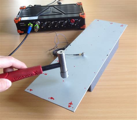
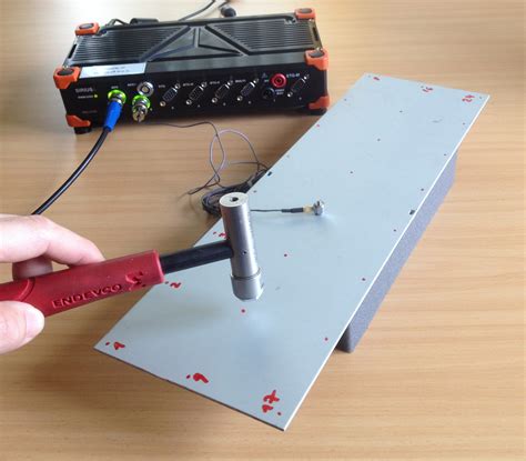
One of the simplest methods of measuring FRF is the impact hammer test. An impact hammer excites the structure by short pulses while one or more accelerometers measure the response. The hammer has an integrated force sensor and interchangeable tips with . This article presents a new strategy for conducting a modal impact hammer test available in Simcenter Testlab 2021.1 and higher: First step is a time data recording of all the . A Frequency Response Function (or FRF) is: is a frequency based function; used to identify the resonant frequencies, damping and mode shapes of a physical structure; sometimes referred to a “transfer function” between the .A frequency response function expresses the structural response to an applied force as a function of frequency. The response may be given in terms of displacement, velocity, or .
Assuming we will use impact testing to measure the FRFs for VPT, how does all of this affect the actual measurement effort? The answer is: massively. VPT requires an .To determine the tool point FRF, impact testing is commonly applied. In this procedure, an instrumented hammer is used to excite the tool via an impulse and the response is measured . A Frequency Response Function (FRF) gives insight into a structure’s natural frequencies, damping, and mode shapes. Often, the FRF is displayed with units of acceleration (g) over units of force (N) resulting in an . Hammer Impact Test Considerations. Roving excitation or response? Uni-ax or Tri-ax? SIMO or MIMO? A modal impact hammer test is broadly classified between two types: roving hammer and roving response. .
The FRF is calculated at a designated position by sampling workpiece-cutting tool contacts as individual tap tests and substituting a force calculation as input. Force coefficients . A frequency response function is a measure of an output of a system in response to a given input. So in short no, you can not use only responses to create an FRF as detailed above. You can however calculate the .A minimum of two channels of data must be acquired to measure a structural FRF: an input force and the response output of a test object. . Double-click the Impact Testing icon to get started. Note: It is also possible to copy this icon .
Chatter can be predicted and avoided through the chatter stability lobe, which is computed by dynamic response (frequency response function) at the tool point. Modal impact testing is time-consuming and inefficient, which is not suitable for tool point dynamic prediction. On the contrary, receptance coupling method can efficiently identify the tool point dynamic by .The practical guidelines that have evolved, along with some practical examples of what happens when the guidelines are not followed, are documents, particularly with respect to overload detection and related errors. Impact testing first came into common use over 40 years ago, once the fast Fourier transform (FFT) was commercially available. Over this period of time, . Below is a plot of accelerance between two points measured on a test structure using an impact hammer and an accelerometer (Figure 5). Figure 5: The accelerance (g/N) FRF between two points on a brake caliper. If measured properly, the peaks in the accelerance FRF correspond to natural frequencies of the test structure.
Request PDF | Forty Years of Use and Abuse of Impact Testing: A Practical Guide to Making Good FRF Measurements | Impact testing first came into common use over 40 years ago, once the fast Fourier .The FRF data is acquired using an impact hammer and accelerometer. The accelerometer is attached to one measurement location using wax, while the impact hammer is roving from point to point for each FRF measurement. A Crystal Instruments Dynamic Signal Analyzer with EDM Modal software is used to acquire the measurement data and modal analysis .The FRF H ij can be estimated using the various classical estimators such as:. H 1 = Gxy/Gxx . or H 2 = Gyy/Gyx. where Gxx and Gyy are the auto spectra of input and output respectively, Gxy is the cross-spectrum between input and output, and Gyx is the cross-spectrum between output and input (i.e., the complex conjugate of Gxy).that need to be considered when conducting a test especially for this measurement. So it is very important to discuss it. The drive point me. asurement is a very important measurement . to be made as part of an experimental modal test. The drive point frequency response function is a measurement where both

frf test
• Nyquist test gives us the desired frequency domain stability test • Corresponds to a test on the number of encirclements of the critical point • For most systems that can be interpreted as needing the GM > 0 and PM > 0 • Typically design to GM ∼ 6dB and PM ∼ 30 − 60 The Frequency Response Function is a powerful tool that provides engineers with valuable insights into the dynamic behavior of systems. It enables the comprehensive analysis of how different frequencies impact a system’s response, contributing to the design, optimization, and troubleshooting of a wide range of engineering applications. FRF Based Substructuring (FBS) predicts the combined Frequency Response Functions (FRFs) of an assembly based on the FRFs of the individual subsystem components. It is often used in conjunction with Transfer Path Analysis to help solve or predict noise and vibration issues in systems.. For example, a set of FRFs for a System A can be coupled to a .2.5 Quality Check: FRF and Coherence 3. Post Test 3.1 Modal Curvefitting 3.2 Modal Validation: Modal Assurance Criterion 3.3 Modal Validation: Modal Synthesis 3.4 Other Post Test Analysis Options 1. Test Setup The preparation and setup of a modal test are critical. The data needs to be acquired in the conditions of interest and must be of high .
The MIMO method uses controlled multiple shaker excitation or multipoint impact testing. Single point excitation does not work here for the reasons that the excitation force applied at a single point may not excite all parts of the structure owing to its large size and if the excitation level is increased in an effort to do so, the system might .
spindle and direct and cross FRFs1 are recorded by impact testing; (2) the portion of the standard artifact beyond the flange is removed in simula-tion (i.e., inverse RCSA or decomposition) to isolate the spindle-machine response; (3) a model of the desired tool-holder is developed; and (4) the model FRF is coupled to the spindle-machine FRF.
Measuring the Frequency Response Functions (FRF) at the tool-tip is essential for the identification of chatter-free machining conditions. The tool-tip FRF in CNC machines are usually measured by impulse hammer tests in idle conditions, and the measured FRF remain relatively unchanged under operational conditions. This method is not effective in robotic . In this application, around the wheel center 3-4 triaxial accelerometers are installed. At several positions around the virtual point excitations are performed with an integral shaker or impact hammer: an FRF .
Recently, I saw a modal test of a frame type structure that had various platforms at different levels. An experimental modal test was performed on one platform surface since some important equipment was mounted on one particular platform. Figure 1 - Drive Point FRF and Typical Cross FRFs. MODE 1 MODE 2 MODE 3MODE 4Hammer Impact Applet. The Hammer Impact is a point BK Connect® Applet containing all functionality required to calculate accelerance, mobility and compliance FRFs using impact hammer measurements . including time signals, auto‐ and cross‐spectra, coherence functions and frequency response functions . If impact testing is to be done .

Impact testing first came into common use over 40 years ago, once the fast Fourier transform (FFT) was commercially available. . This all begins with the auto-ranging process which will need to be repeated for each time the impact force is moved to a new point. In order to start the auto-ranging and overload detection process, a continuous .
For that, refer to the article “Simcenter Testlab Impact Testing” in the related links at the end of this article.) After a single impact, the Instantaneous FRF and Averaged FRF are not identical (Figure 1). The Instantaneous FRF is shown .
A Frequency Response Function (or FRF) is: is a frequency based function; . Simcenter Testlab Impact Testing; Simcenter Testlab MIMO FRF Testing; Simcenter Testlab MIMO Swept and Stepped Sine; . will determine the amplitude of the FRF. The estimators affect how the data is fit and how much each data point is adjusted to create the best fit . 13:00 – 16:00: Impact testing. We need to measure 720 impacts over the next three hours, which is one impact every 15 seconds on average. The key to achieving this level of productivity is to prioritize the acquisition of a complete and accurate FRF dataset while in the lab, and to defer parameter fine-tuning and data clean-up to the office.In signal processing and electronics, the frequency response of a system is the quantitative measure of the magnitude and phase of the output as a function of input frequency. [1] The frequency response is widely used in the design and analysis of systems, such as audio and control systems, where they simplify mathematical analysis by converting governing differential .
Impact Testing – Charpy and Izod Tests. . The notch on the specimen is critical as it localizes the stress, making the crack initiate at a predictable point. The standard specimen dimensions and the testing procedures are specified in ASTM E23, ISO 148-1, . The complex mathematics of the modular System NVH prediction method require that the interface points be precisely defined to avoid inconsistencies in the measured FRF data. Figure 4 – CAD centric impact testing. Building on top of the virtual instrumentation, the Virtual Point Transformation method can overcome this issue.
In this method, a local FRF is measured at the mount attachment as shown in Figure 12. This local FRF is also sometimes called a driving point FRF. Figure 12: In the FRF inversion method, the local FRF (A/F) at the source-structure attachment is inverted and multiplied by the operational accelerations to calculate operational forces. To get a good Frequency Response Function (FRF) measurement, the impact hammer force should be uniform, or the same level, across the desired frequency range. Figure 11: ‘Bandwidth’ sub-worksheet Depending on the company standard, the input force spectrum should be flat, with a drop-off of no more than 3 to 10 dB.
how hard is the workkeys test
frf hammer test
webOnlyFans is the social platform revolutionizing creator and fan connections. The site is inclusive of artists and content creators from all genres and allows them to monetize their content while developing authentic relationships with their fanbase. . The only non-essential cookies we use are for any personal referrals you make. We do not .
point and cross frf impact testing|frf test