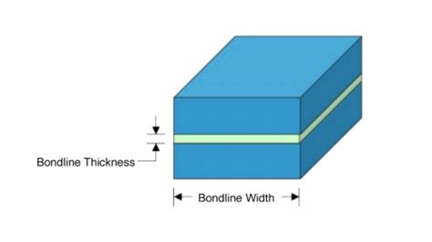
bond line thickness measurement|bond line thickness die attach : vendor Typical measurements include bond line thickness measurement (BLT), die tilt determination, torsional information, BLT height or die/chip placement, and relative measurement to a reference position.
WEB13 de nov. de 2023 · MORTA NOS PECADOS, RENASCIDA EM DEUS! JORDANA VUCETIC #MAISFORTEPODCAST. KARINA BACCHI. Neste trigésimo primeiro episódio, temos a grande .
{plog:ftitle_list}
WEBu/sarahstanislau. • 2 mo. ago GRUPO DE PUTARIA TELEGRAM, GOSTOSAS DO TIKTOK, GOSTOSAS DO ONLYFANS, DANÇANDO DE SHORTINHO, SARAH ESTANISLAU, MARI LADEIRA, CATARINA PAOLINO, LOIRAS GOSTOSAS,DEBORA PEIXOTO, FRACISSIMAS, CIBELLY FERREIRA, ONLYFANS GRATIS ENTRE .


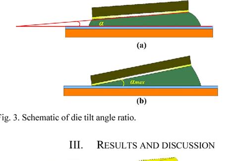
The standard bond thickness for both films is 0.003 inches. However, they can be formulated in custom sizes and thicknesses. Need technical assistance? Learn more about the importance .Figure 7 shows the results of bond line thickness and die tilt measurement. The results show the good and controllable bond line thickness and die tilt. .
minimum bondline thickness
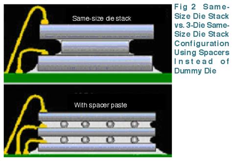
In addition, best practices include preparing the surface properly and achieving the appropriate bond line thickness. When designing, building or repairing a structure that relies on bonded . To control bond line thickness, get your adhesive premixed and frozen with glass spacer beads added for even disbursement. The advantage of spacer beads is the elimination of process variables and risk. Because you’re .To ensure a specific bond line thickness in materials, glass beads are often used. These are small spheres that are added at approximately 1% of the formulation weight to maintain the desired thickness for the application when . Typical measurements include bond line thickness measurement (BLT), die tilt determination, torsional information, BLT height or die/chip placement, and relative measurement to a reference position.

Choosing the best thermal compound requires some understanding of the mechanics of heat transfer and how the thickness of the thermal compound layer, the bond line thickness, influences product choice. Bond line can be divided into three categories: Low, at less than 75 μm; Medium, from 75 to 250 μm; High, at greater than 250 μm
The present investigation describes about the development of a cost effective measurement technique for automatic determination of bond-line thickness and die tilt in die attach for semiconductor .Bond line thickness control. Controlling the thickness of the adhesive bondline is a critical factor in bond strength. This control can be obtained by matching the quantity of available adhesive to the size of the gap between the mating surfaces under actual bonding conditions (heat and pressure). From the load–penetration curve we can easily obtain the maximum displacement, h max, the maximum load on the sample, P max and the contact stiffness, S. S is the slope of the tangent line to the unloading curve at the maximum loading point. The contact depth, h c is related to the deformation behaviour of the material and the shape of the indenter. In fact h c . Abstract This study focuses upon building an automated inspection system for the in-line measurement of bond-line thickness (BLT) and die tilt in die attachments in the semiconductor packaging process. A prototype of a visual system utilizing the line scan stereo vision technique via two linear CCD cameras has been developed for the die bonding quality .
The adhesive examined here is a two-part system. An amount of 100 parts by weight of a diglicidyl ether of bisphenol A (DGEBA) epoxy pre-polymer are mixed with 40 parts of trioxatridecane diamine (TTD) hardener, previously marketed as Redux 420, now Araldite 420 supplied by Huntsman. This adhesive has been widely used for many years, in both the .to test TIMs at controlled bond line thickness BLT and con-trolled pressure, while being able to directly measure the bond line thickness. Solbrekken’s tester can be used to measure the thermal impedance of a TIM with the minimum measurable limit of 0.03 K cm2/W at a 95% confidence level. Zhang et al. devel-
The following is a suggestion of minimum bond line thickness as a function of adhesive type and application: ADHESIVE TYPE MINIMUM BOND LINE THICKNESS COMMENTS Silver-filled 12 micron (0.5 mil) – Less than this can become electrically insulating – Best thermal pathway is .We use a PATTI device to measure tensile adhesion. This device pulls on bonded studs perpendicular to the surface and measures the load required to pull them off. . In addition, best practices include preparing the surface properly and achieving the appropriate bond line thickness. When designing, building or repairing a structure that relies .The adhesive thickness or also bond line thickness (BLT) is key for a reliable die attach to a lead frame or other substrates. TopMap surface profilers from Polytec allow an automatic and reliable determination of the die orientation on the lead frame including the die tilt as well as bond line thickness measurement.
In-situ measurement of various thin bond-line-thickness thermal interface materials with correlation to structural features October 2008 DOI: 10.1109/THERMINIC.2008.4669890 In the toughness approach, the interest lies in the measure of the energy levels at which the joints fail and the crack propagates. . Influence of adhesive bond line thickness on joint strength. Int. J. Adhes. Adhes., 29 (7) (2009), pp. 724-736. View PDF View article View in Scopus Google Scholar [10] Hybond Inc.’s patented bond-line thickness measurement and die placement technology is incorporated on its model EDB-141 die bonder to greatly improve yields and thermal performance of critical die. The Hybond . The present investigation describes about the development of a cost effective measurement technique for automatic determination of bond-line thickness and die tilt in die attach for semiconductor packaging process. Bond line thickness (BLT) and die tilt in the die attach were measured using an optical non contact scanning probe system.
Fig. 6(a) illustrates the measured Δ T(t,x) of the test chip and the diode for the Ag-sintered sample with a bond line thickness of approximately 33 μ m, along with the applied input power. The measurement data of the test chip shows a lower signal-to-noise ratio, indicating higher fluctuation compared to the diode measurement. The present investigation describes about the development of a cost effective measurement technique for automatic determination of bond-line thickness and die tilt in die attach for semiconductor .Table 1: Nominal bond line specifications for the four bonded composite specimens and micrometer point estimates for adherend thickness. All measurements are in centimeters. Specimen Image location (Fig.1) Adherend thickness Nominal bond line thickness Adhesive layers 1 Top left 0.181 0.025 6 2 Top right 0.183 0.15 17 3 Bottom left 0.182 0.1 12 For a bond line thickness h greater than R 0, which is a material-based length scale, TH showed that Γ eff becomes independent of the bond line thickness. R 0 is approximately the plastic zone size as long as \( {R}_0{\Gamma}_0 \) for large scale bridging, the plastic zone size scales with R 0.
Quantifying the bond thickness allows for confidence that loading is being properly transferred. This study presents a methodology to measure bondline thickness using the data obtained from an immersion quality ultrasound scan using an out-of-tank, field-portable, utlrasonic testing (UT) scanner. Eighteen bonded coupons were fabricated using a .
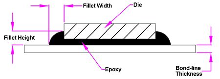
The corresponding inverse problem of estimating bond line thickness from measurement data was solved using a Bayesian approach that assumed Gaussian priors for the bond line thickness and thermal diffusivity of the adherends. Finally, the outputs of the thermography based method were compared to measurements that were collected using a .The use of epoxy glue die attach material to bond s ilicon die onto a substrate or lead frame in an IC (integrated circuit) package is still very popular. But there are differ ent challenges associated with using glue die attach li ke the need to control bond line thickness (BLT), fillet h eight, voiding and bleed out. Reliability issues like dela mination could happen when there is problem .
bond line thickness as a function of adhe-sive type and application: Adhesive Type Minimum Bond Line Thickness Comments Silver-filled 12 micron (0.5 mil)-Less than this can become electrically insulating-Best thermal pathway is 0.5 to 3 mils - Die attaching and SMD caps and resistor mounting Thermally conduc-tiveWe designed an infrared optical system to measure the thickness of Si without damaging the wafer and chips. Infrared ray has good light transmission property for silicon, so we can get the images Park, Y., Kang, K., Yun, S. and Kim, S. The Method to Measure Si Thickness for Bond Line Thickness. DOI: 10.5220/0006525502730275
epoxy fillet height
Thermal characterisation of thermal interfaces becomes even tougher a challenge at low bond line thicknesses and higher thermal conductivities of the interface materials as more accurate measurement techniques are required. As in parallel the quest for high conductivity adhesives and greases is ongoing, a correlation between thermal bulk or interface properties and .

Laboratory Rotary Digester convenience store
die tilt
SLOT.VIP The ONE AND ONLY LEADING gaming brand in Philippines!slot games, Fish Game , Sports Betting, Slot Casino, Online Games, sabong, - SLOTVIP.Ph Join Now And Start Winning Jackpot. NEW PLAYER JOIN+₱888. LIVE CHAT; Messenger .
bond line thickness measurement|bond line thickness die attach