torsion test mohr's circle|torsion test examples pdf : discounter Mohr’s circle is a powerful graphical method used to visualise and analyze the stress state at a single point within a body. It allows you to determine the normal and shear stress components for different orientations of the stress . WEBO Apoie-um-Criador é um programa de marketing de afiliados para streamers e criadores de conteúdo de redes sociais. O programa dá aos criadores a oportunidade de receber .
{plog:ftitle_list}
No Reclame AQUI, empresas ruins, não recomendadas e em análise não são anunciadas. Caso veja alguma, não deixe de nos avisar: [email protected]. Saiba se a empresa BITCOIN TO YOU é confiável, segundo os consumidores. Se tiver problemas, reclame, resolva, avalie. Reclame Aqui.
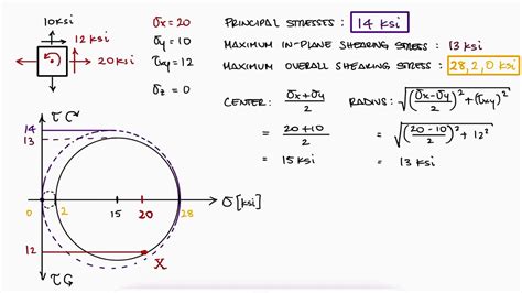
Mohr's circle is a two-dimensional graphical representation of the transformation law for the Cauchy stress tensor. Mohr's circle is often used in calculations relating to mechanical engineering for materials' strength, geotechnical engineering for strength of soils, and structural engineering for strength of built structures. It is also used for calculating stresses in .The equations for plane stress transformation have a graphical solution, called Mohr’s circle, which is convenient to use in engineering practice, including “back-of-the-envelope” calculations. Mohr’s circle is plotted on a coordinate system:Mohr's Circle for Torsion provides a visual tool for determining maximum shear stress and angle of twist in non-circular members under torsional loads. In Mohr's Circle, the center represents .Mohr's circle serves as a powerful graphical tool for visualizing and analyzing these stress states. This method helps engineers determine principal stresses (maximum and minimum normal .
Mohr’s circle is a powerful graphical method used to visualise and analyze the stress state at a single point within a body. It allows you to determine the normal and shear stress components for different orientations of the stress .
Torsion. In this case, the rod is subjected to a torque (twisting force) at either end: How do you imagine the element would stretch this time? Answer: The left side of the square .The failure boundary in the σ P1 vs. σ P2 plane is given by: σ P1 / σ UT - σ P2 /σ UC = 1. The animation below shows how Mohr's circle changes in position and size as we move around the perimeter of Mohr's failure boundary.
Mohr's circle can be used for convenient representation of 3 dimensional stress strain distributions. A typical Mohr's circle diagram is shown below: Mohr's circles representing . Mohr's circle helps analyse this. For now, only the first two ways will be analysed. 1.Tension/compression: . Torsion . In this case, the rod is subjected to a torque (twisting force) at either end: How do you imagine the element would stretch this time?
torsion test examples pdf
In this video, we're going to take a look at stress transformation and Mohr’s circle.Stress transformation is a way of determining the normal and shear stres.m) or foot-pound force (ft5. Draw a line from point A to point B, a diameter of the circle passing through point c. Points A and B (representing stresses on planes at 90° to each other) are at opposite ends of the diameter (and therefore 180° apart on the circle). 6. Using point c as the centre, draw Mohr’s circle through points A and B. This circle has radius R .
Obtain The Center Of The Mohr’s Circle: 5. The center of the Mohr’s circle is obtained graphically by plotting the two points representing the two known states of stress, and drawing a straight line between the two points. The intersection of this straight line and the -axis is the location of the center of the circle. Draw The Mohr’s .
Draw a stress Mohr circle for each test (let the specimen axis, i.e. longitudinal direction, be x-axis and the transverse direction be y-axis) and express both the maximum principal stress (σmax) and the maximum shear stress (τmax) in terms of σ (for tension test) or τ (for torsion test). Mark the x-axis on the Mohr’s circle.

Intro and Derivation Mohr’s circle is a geometric representation of plane (2D) stress transformation and allows us to quickly visualize how the normal (σ) and shear (τ) stress components change as their plane changes orientation. German civil engineer Otto Mohr developed this method from the good ol' stress transformation equations. Draw a stress Mohr circle for each test (let the specimen axis, i.e. longitudinal direction, be x-axis and the transverse direction be y-axis) and express both the maximum principal stress (σ max ) and the maximum shear stress (τ max ) in terms of σ (for tension test) or τ (for torsion test). Mark the x-axis on the Mohr’s circle.Draw a stress Mohr circle for each test (let the specimen axis, i.e. longitudinal direction, be x-axis and the transverse direction be y-axis) and express both the maximum principal stress (sigma_max) and the maximum shear stress (tau_max) in terms of sigma (for tension test) or tau (for torsion test). Mark the x-axis on the Mohr's circle. Also .Draw a stress Mohr circle for each test (let the specimen axis, i.e. longitudinal direction, be x-axis and the transverse direction be y-axis) and express both the maximum principal stress (sigma_max) and the maximum shear stress (tau_max) in terms of sigma (for tension test) or tau (for torsion test). Mark the x-axis on the Mohr's circle.
About Press Copyright Contact us Creators Advertise Developers Terms Privacy Policy & Safety How YouTube works Test new features NFL Sunday Ticket Press Copyright .Mohr's circle serves as a powerful graphical tool for visualizing and analyzing these stress states. This method helps engineers determine principal stresses (maximum and minimum normal stresses), extreme shear stresses, and their corresponding angles. The circle provides a complete visualization of how stresses transform when an element is .a. Let the tensile stress in a tension test be σ and the shear stress in a torsion test be t. Draw a stress Mohr circle for each test (let the specimen axis, i.e. longitudinal direction, be x-axis and the transverse direction be y-axis) and express both the maximum principal stress (omax) and the maximum shear stress (Trax) in terms of σ (for tension test) or τ (for torsion test).The animation below shows how the Mohr’s circle changes as we move around on this hexagonal-shaped boundary between safe and failure. Observations. In quadrant 3 of the principal stress plane, Mohr's circle is in the left-half plane with the .
Ch. 6 Torsion 5 / 17 à When shaft is twisted, it is on the pure shear stress state. And a convenient way to determine these stress components is to use Mohr’s circle for stress. We may use the two-dimensional Mohr’s circle because there is no stress in the -direction. Magnitudes of principal stresses (from Mohr circle) | |=|σ axis establishes the center of the circle. 8. Draw the complete circle. 9. The line from the center of the circle to point V identifies the x axis or reference axis for angle measurements (i.e. θ = 0). Note: The angle between the reference axis and the σ axis is equal to 2θ p. Mohr’s Circle:Conclusion. In conclusion, Mohr's Circle is a valuable tool in geotechnical engineering that allows for the graphical representation and analysis of stress and strain relationships. By using this method, engineers can gain valuable insights into the behavior of soil and rock materials, enabling them to make informed decisions in the design and construction of infrastructure projects.a. Let the tensile stress in a tension test be σ and the shear stress in a torsion test be τ. Draw a stress Mohr circle for each test (let the specimen axis, i.e. longitudinal direction, be x-axis and the transverse direction be y-axis) and express both the maximum principal stress (Omax) and the maximum shear stress (tmax) in terms of σ (for tension test) or τ (for torsion test).
Mohr circle for each test (let the specimen axis, i.e. longitudinal direction, be x-axis and the transverse direction be y-axis) and express both the maximum principal stress (σ max ) and the maximum shear stress (τ max ) in terms of σ (for tension test) or τ (for torsion test). Mark the x-axis on the Mohr’s circle.
Consider the tensile stress in a tension test as σ and the shearstress in a torsion test as τ. Draw a stress Mohr circle for each test, with the specimen axis (i.e., longitudinal direction) as the x-axis and the transverse direction as the y-axis. Express both the maximum principal stress (σmax) and the maximum shear stress ( τmax) in terms .
Let the tensile stress in a tension test be σ and the shear stress in a torsion test be τ. Draw a stress Mohr circle for each test (let the specimen axis, i.e. longitudinal direction, be x-axis and the transverse direction be y-axis) and express both the maxim um principal stress (σ max ) and the maximum shear stress (τ max ) in terms of σ .This is a special case for Mohr's circle, The coordinate origin is located in the center of Mohr's circle. The normal stress changes from tension (positive) to compression (negative). The red color 's state of stress on the right corresponding to the red point on the circumference on the left.You can determine the positive direction of the angle \(2 \varphi\) in Mohr's Circle for a desired combination of the coordinate system used and the \(\tau\)-axis direction by using the formula 1.5xy or 1.5xz, depending on the used coordinate system.Insert any positive or negative normal stress \(\sigma_x\) and a positive cutting angle \(\varphi = 45°\)."
Question: c. 3. Question a. Let the tensile stress in a tension test be σ and the shear stress in a torsion test be t. Draw a stress Mohr circle for each test (let the specimen axis, i.e. longitudinal direction, be x-axis and the transverse direction be y-axis) and express both the maximum principal stress (omax) and the maximum shear stress (Tmax) in terms of σ (forQuestion: In a torsion test, a maximum shear stress of 90MPa is generated in the sample at the surface of the sample. Calculatethe hydrostatic stress in the sample. (you may need to use the Mohr circle)
Main Video: Mohr's Circle Review for Mechanical Design in Just Over 10 Minuteshttps://youtu.be/Xc3VzDy5Ik4Example 1: https://youtu.be/jYVwxqbFR4QExample 2: h.Mohr's Circle is a graphical method used in engineering to represent the state of stress at a point in a material. It provides a visual representation of the normal and shear stresses acting on a material, allowing engineers to analyze and understand the stress conditions. By plotting these stresses on a circle, engineers can easily determine .
tibial torsion special test

tibial torsion test infant
A group of high school students navigate love and friendships in a world of drugs, sex, trauma, and social media.
torsion test mohr's circle|torsion test examples pdf